|

|
Operational Information
Fatigue
|
****JavaScript based drop down DHTML menu generated by NavStudio. (OpenCube Inc. - http://www.opencube.com)****
|
|
A
metal subjected to a repetitive or fluctuating stress will fail
at a stress much lower than that required to cause fracture on a
single application of load. Failures occurring under conditions
of dynamic loading are called fatigue failures, presumably
because it is generally observed that these failures occur only
after a considerable period of service. Fatigue accounts for at
least 90 percent of all service failures due to mechanical
causes.
Fatigue occurs when a
material is subject to alternating or cyclic stresses, over a
long period of time. Examples of where fatigue may occur in a
marine diesel engine are: crankshafts, valve springs,
turbocharger blades, piston crowns, bottom end bolts, piston
skirts at the gudgeon pin boss and tie bolts.
Stresses can be applied
in three ways, torsionally, axially and by bending.
The symbol for
stress is the Greek letter sigma s
and the units are force/ unit area i.e N/m2 or psi
(imperial)
|

|
TORSIONAL
This is where the
material is twisted and untwisted along its axis. Any
rotating shaft driving a load will be subject to torsional
vibration at the natural frequency of the shaft. However
torsional vibration is most easily visualised in an engine
crankshaft where the compression and firing forces are
applied to the crankpin through the piston and con rod.
These forces vary according to angle of
thrust applied by the conrod and the cylinder firing
pressure but are greatest at about 10° either side of TDC.
The
crank also has to absorb the inertia loading due to the
conrods and pistons, which easily amounts to several tons on
each cylinder.
|
|

|
AXIAL
This is where the
material is subject to tension or compression along its
axis. An example of this are the bottom end bolts on a four
stroke engine.
The bolts and their nuts are subject to
tensile stress when tightened and additional varying tensile
stress during operation. The total stress level is high and
varies with time, giving rise to the risk of fatigue. The
connecting rod is in compression during the compression and
power strokes, but due to the inertia forces in the running gear
when the piston changes direction between the exhaust and inlet
strokes, the connecting rod is put into tension. This increases
the tension in the bottom end bolts, leading to cyclic
stressing. |
|

|
BENDING
When
material is bent, the inside of the bend will be in
compression and the outside of the bend will be in tension.
This type of stress can be easily visualised in a piston
crown under the gas load and is compounded by the stresses
induced by the difference in temperature on the top surface
and the underside of the crown (thermal stressing).
It also
occurs in crankshafts where the gas load on the piston is
bending the crankshaft. If the main bearings are of
different heights (i.e out of vertical alignment), then the
bending is increased. |
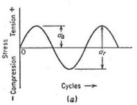
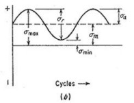
STRESS CYCLES
There are three stress cycles with which loads may be applied to the component
under consideration. The simplest being the reversed stress cycle . This is
merely a sine wave where the maximum stress and minimum stress differ by a
negative sign. An example of this type of stress cycle would be in an axle,
where every half turn or half period as in the case of the sine wave, the stress
on a point would be reversed. The most common type of cycle found in engineering
applications is where the maximum stress (smax)and
minimum stress (smin) are asymmetric (the
curve is a sine wave) not equal and opposite. This type of stress cycle is
called
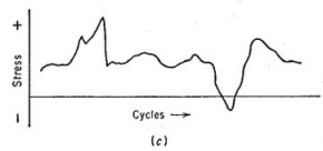
repeated stress cycle. A final type of cycle mode is where stress and
frequency vary randomly. An example of this would be hull shocks, where
the frequency magnitude of the waves will produce varying
minimum and maximum stresses.
THE S-N CURVE
|
The S-N curve is just
a graph plotted of stress, S against the number of cycles N.
N is a logarithmic
scale i.e 105 cycles, 106 cycles 107
cycles etc.
The line plotted for the particular material will indicate
how many stress reversals it can go through before it fails.
If the material is loaded below the fatigue limit, which in
the example shown is 14×103 psi (95×103
kN/m2) then it will not fail
regardless of the number of stress cycles.
Material such as aluminum, copper and magnesium do not show
a fatigue limit, therefore they will fail at any stress and
number of cycles. Other important terms are fatigue strength
and fatigue life. The stress at which failure occurs for a
given number of cycles is the fatigue strength. The number
of cycles required for a material to fail at a certain
stress is the fatigue life.
|

|
CRACK INITIATION,
PROPAGATION AND FAILURE
Failure of a material due
to fatigue may be viewed on a microscopic level in three steps:
-
Crack Initiation:
The initial crack occurs in this stage. The crack may be
caused by surface scratches caused by handling, or tooling of
the material; threads ( as in a screw or bolt), flaws in the
material, slip bands or dislocations intersecting the surface
as a result of previous cyclic loading or work hardening.
-
Crack Propagation:
The crack continues to grow during this stage as a result of
continuously applied stresses
-
Failure: Failure
occurs when the material that has not been affected by the
crack cannot withstand the applied stress. This stage happens
very quickly.
|
 |
Fatigue failure can
be identified by examining the fracture. A fatigue fracture
will have two distinct regions; One is smooth or burnished
as a result of the rubbing of the bottom and top of the
crack as it is growing. The second is granular, due to the
rapid failure of the material. |
|
Other features of a
fatigue fracture are Beachmarks and Striations. Beachmarks,
or clamshell marks, may be seen in fatigue failures of
materials that are used for a period of time, allowed to
rest for an equivalent time period and the loaded again as
in factory usage. Striations which can be seen through a
microscope, are thought to be steps in crack propagation,
were the distance depends on the stress range. Beachmarks
may contain thousands of striations |
 |
|

Visible beachmarks on a
tiebolt failure |

Magnification of fatigue
failure showing striations |


|