|

|
Operational Information
The Medium Speed 4 Stroke Trunk Piston
Engine
The Fuel Pump
|
****JavaScript based drop down DHTML menu generated by NavStudio. (OpenCube Inc. - http://www.opencube.com)****
|
|
SEE ALSO THE
TWO STROKE CROSSHEAD ENGINE FUEL PUMP
|
Medium speed four stroke engines are equipped with
jerk type fuel pumps, one for each cylinder. A plunger operated
by a cam reciprocates in a barrel.
The plunger has a helix machined
into it which also forms a vertical groove and an annular groove at the
base of the helix. The barrel is located in the
pump body which has spill ports, connected to the suction side of the
pump, drilled so that they are above the top of the plunger when the cam
is on the base circle. The plunger is keyed to a sleeve which has a
gearwheel (pinion) machined into it. The pinion meshes with a rack which
can rotate the plunger relative to the barrel. The rack is connected to
the engine governor. |
 |
As the plunger moves upwards in the barrel, injection will commence
once the plunger has closed off the spill ports and the pressure builds
up. As soon as the helix or scroll passes the spill ports the pressure
above the plunger will immediately drop, even though the plunger is still
moving upwards. It should therefore be evident that the amount of fuel
injected into the cylinder is dependent on the position of the helix
relative to the spill port. When the vertical groove is lined up with the
spill port, then no injection will take place and the engine will stop.
 |
In the example shown above the plunger has a single helix machined into it.
More common are pumps with two helices (and thus two no load grooves)
diametrically opposite each other. This gives a balanced plunger. (shown
left) |
|
The plunger is machined to very fine tolerances, as is the matched
barrel in which it reciprocates. Wear due to abrasive particles in the
fuel will mean that the pump will take longer to build up the injection
pressure required. Wear due to erosion also takes place on the top edge of
the plunger and the edge of the helices and spill ports. This, together
with the wear in the plunger and barrel, will lead to the injection timing
becoming retarded, for which adjustment may have to be made. |
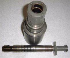
Plunger and barrel from a Sulzer ZA40 |
On the scroll or helical fuel pump, although the end
of injection can be varied, the start of injection (i.e. when the top of
the plunger covers the spill ports) is fixed. Fuels of different qualities
may require advancing or retarding the start of injection, in addition to
which if the injection timing is advanced when the engine is running at
loads below the maximum continuous rating, then a saving in fuel can be
achieved.
Different engine manufacturers achieve this Variable Injection Timing (VIT)
using different methods.
|
The Wartsila 64 engine uses a fuel pump with two
plungers and two barrels with common suction and discharge. The
plunger for controlling the start of injection (timing) has a
helix in the top of the plunger, while the plunger for
controlling the end of injection (metering) is a conventional
scroll type fuel pump plunger.
Both plungers are operated by the same cam. As they move
upwards in their respective barrels injection will not start until
the helix on the timing plunger has covered the spill port. This
point is controlled by rotating the plunger in the barrel by
means of a rack and pinion.
End of injection is controlled in the normal way, when the
helix on the metering plunger uncovers the spill ports.
|
 |
 |
The MAN B&W 32/40 engine has a separate camshaft
for the fuel pumps that can be advanced or retarded as the engine
is running. The final drive gear on the timing gear train has an
internal helically toothed sleeve bolted to it. The gear wheel and
sleeve can be moved axially by means of a hydraulic piston. The
toothed sleeve meshes with a matched helical gear fixed to the
camshaft.
The camshaft is fixed so that it cannot move axially. Therefore
as the sleeve moves up and down controlled by the hydraulic
piston, so the fuel pump timing is advanced or retarded.
The camshaft for the inlet and exhaust valves utilises two
different profiles for economy and full power operation. The
camshaft can move axially from one set of cams to the other whilst
the engine is running similar to the method used for reversing the
engine direction as shown on the camshaft page. |


|