|

|
Operational Information
The Medium Speed 4 Stroke Trunk Piston
Engine
The Rocker
Gear and Valves
|
****JavaScript based drop down DHTML menu generated by NavStudio. (OpenCube Inc. - http://www.opencube.com)****
|
|

The 4 stroke marine diesels used for main or auxiliary
power on board ship will have multiple inlet and exhaust valves fitted
to the cylinder heads. On the medium speed engines this normally takes
the form of two inlet and two exhaust valves per unit. The reasons for
this are as follows:
-
The area of the valve openings must be large enough
to provide for an efficient gas exchange process. If the area is too
small then not enough air will be pushed/drawn into the cylinder
during the induction stroke, and on the exhaust stroke the engine
will be doing work pushing the exhaust gas out of the cylinder.
-
The cylinder head must accommodate inlet and exhaust
valves, so unlike a two stroke engine, one large central exhaust
valve is not possible.
-
If the valves are too large, then the strength of
the cylinder head will be compromised.
-
Keeping the exhaust valve temperature within
acceptable limits is of paramount importance. It is easier to cool a
smaller valve.
-
The moving parts and springs are of smaller
proportions reducing the inertia of the parts and the power demand
on the engine.
-
A symmetrically designed strong cylinder head
is achieved.
 |
Exhaust valves are subject to arduous conditions,
and require regular overhaul. To aid this, exhaust valves are
often fitted in separate cages. This allows the exhaust valve to
be changed and overhauled without removing the cylinder head. The
cages have water cooling passages connected to the cylinder head
cooling water.
The cage is of cast steel. The cooled seats are made from a
heat resistant molybdenum steel which may be stellite faced. The
exhaust valve may be of a similar material or of a nimonic alloy. |
Inlet valves are subject to much less arduous conditions
and are not usually fitted in separate cages.
Two different sized springs are fitted to aid positive
closing of the valves. The reason for fitting two springs are that if
one fails, the other will prevent the valve dropping down into the
cylinder. The two springs have different vibration characteristics, so
the incidence of resonance is reduced. (resonance is where two items
vibrate at the same frequency thus the amplitude of the vibration is
amplified.)
Exhaust valves are designed to rotate in service. The
reasons for this are to prevent uneven temperatures so it does
not distort and leak by, and to help dislodge any build up of
deposits on the valve and seat which may prevent the valve closing
properly and lead to "hammering" of the seating faces. A
mechanical method is generally used, and this is either the
"rotocap"
or the "turnomat". Winged rotators or spinners as used on the
2 stroke engine exhaust valves can also be used, but this entails using
a ball bearing race between the spring carrier and the cover.
Burning Out of Exhaust Valves
|
Once an exhaust valve does not seat correctly, the
high pressure burning gas will pass across the faces of the
valve and seat during the power stroke. This will cause the
temperature of the valve and seat to rise in this area,
weakening the material and distorting the surfaces. The velocity
of the burning gas will erode the surface, allowing more
gas to leak by. The temperature of the valve in this area will
rise further, leading to further burning and greater distortion.
The first indication of a valve burning out will be a rise in
the exhaust temperature, which will rapidly increase together
with a loss of power from the unit. |
 |
Vanadium slag deposits which occur at temperatures above
540º C cause corrosion of the valve surfaces which can lead to exhaust
gas blow by. This is combated by effective cooling and the use of
suitable materials (stellite and nimonic alloys).
Rocker Gear

Master and Slave |
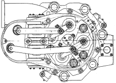
Most medium speed four strokes use
push rods and rocker gear to open and shut the valves at the
correct time. Operated by cams, mechanically timed to the
crankshaft, the pushrods transmit the motion to the rocker gear,
which pushes the valves open at the correct time. Because there
are two of each valve mounted in the cylinder head, the rocker
gear must operate both valves simultaneously. Various methods
are used including master and slave arrangements (Sulzer ZA40)
and yoke (Fiat).
A hydraulic operating system was introduced in place of push
rods and rocker gear on the Sulzer ZA50. This had the advantage
of being able to adjust the timing of the closing of the valves
to suit operating conditions.
|

Yoke
|
Rocker or Tappet Clearances
|
Rocker or Tappet clearances refer to the clearance
between the top of the valve spindle and the rocker arm. It is
to ensure that the valve closes properly when it expands as it
gets to operating temperature. Clearances are set according to
manufacturers instructions, but usually done with the engine
cold, and with the push rod follower on the base circle of the
cam. (one way of ensuring this is to turn the unit being
adjusted to TDC on the power stroke.)
If the clearance is too small, then not only is there a
chance that the valve will not close properly when it comes up
to temperature, but it effectively will open early and close
late.
Conversely if the clearance is too large, then the valve will
open late and close early |
 |


|


